Bafang Bike Motor,Bbs02 Replace Motor,Bafang Mid Motor Parts,Spare Parts For Bafang Changzhou Mayebikes Co.,Ltd , https://www.mayebikes.com
The 80,000-ton/year gas separation unit of the Lanxing Petrochemical Company Tianjin Petrochemical Plant was put into operation in 2005. It used the WebFieldJX-300X system from Central Controls as the control and inspection system, and the vortex flowmeter was used in the flow meter. The main detection loops for liquid hydrocarbon media include: C4 discharge device flow rate, propane product discharge device flow rate, propylene product discharge device flow rate, and liquefied gas (LPG) inlet device flow rate and other liquid hydrocarbon media. The density of this type of medium is greatly influenced by the temperature (pressure stability), resulting in a large deviation between the design conditions of the device and the actual working conditions. At this time, it is not suitable to use the standard compensation module provided by the SUPCON JX-300X system to perform calculations. Complex formulas perform compensation operations.
Analysis and Implementation Methods Mass Flow The mass flow formula is the volumetric flow rate multiplied by the medium:
G actual = qv x γ actual (1)
G design = qv x gamma design (2)
Assuming that the density compensation coefficient of the vortex flowmeter is linear with the temperature, equation (1)/formula (2) is obtained:
G actual/G design=(qv×γ design)/(qv×γ design)
= γ Actual / γ Design = Ï Actual / Ï Design (3)
G actual = (Ï actual / Ï design) × G design = k × G design (4)
Where: k-density compensation coefficient, that is, Ï actual / Ï design (5)
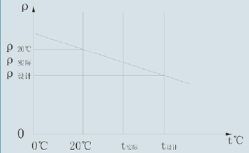
Since the density and specific gravity of a liquid are linearly related to temperature, it can be represented by a linear equation (see Figure 1): 
Figure 1 The linear relationship between density and temperature.
k'=(Ï design-Ï20)/(t design-20°C)(6)
Where: k' - the slope of the line.
So the linear equation is:
Ρactual=k'×(tactual-t design)+Ïdesign(7)
The compensation coefficient in the formula is:
k=Ïactual/Ïdesign=[k'×(tact-tdesign)+Ïdesign]/Ïdesign=k'×(tact-tdesign)/Ïdesign+1
= (k'/Ï design) × (t actual-t design) +1
=k''×(t actual-t design)+1(8)
In equation (8):
k''=k'/Ï design (9)
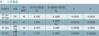
The calculation data is shown in Table 1. 
The calculation results are as follows:
FT-101 temperature compensation coefficient k=1-0.00310×(t-40);
FT-210 temperature compensation coefficient k=1-0.00310×(t-40);
FT-212 temperature compensation coefficient k=1-0.00236×(t-67);
FT-229 temperature compensation coefficient k=1-0.00401×(t-40);
FT-232 temperature compensation coefficient k=1-0.003362×(t-40). 
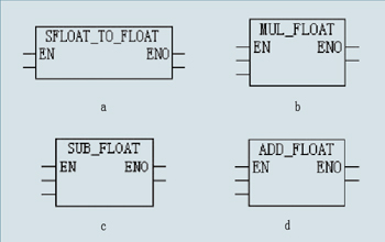
The function of module a is to convert SFLOAT type input values ​​to FLOAT type output values.
The function of module b is to multiply the input floating point value and assign the result to the output floating point value.
The function of module c is to subtract the input floating point value and assign the result to the output floating point value.
The function of module d is to add the input floating-point values ​​and assign the result to the output floating-point value.
The specific implementation scheme is shown in Figure 3 (take K210 as an example). 
Figure 3 shows a specific embodiment.
The calculated mass flow is given by equation (4):
G Actual Calculation = k × G Design G Actual - After compensation real mass flow kg/h
G design - mass flow before compensation kg/h
K—coefficient of compensation coefficient The coefficient “k†in the equation k is the actual operating temperature of the medium in °C.
Density compensation of the volume flow meter The density compensation of the flow meter is calculated as: (when the signal from the transmitter represents the volume flow unit m3/h)
G actual = gamma operation × Q measurement γ operation = (γ design - γ 20) ÷ (t design -20) × (t - 20) + γ 20
In the formula:
G actual - real mass flow after compensation kg/h;
Q measurement—measured volumetric flow m3/h from the flow transmitter before compensation;
t Design—Flowmeter design temperature °C;
T—actual operating temperature in °C from the temperature measurement point before the flow transmitter;
γ design - the density of the medium at the design temperature of the flowmeter kg/m3;
γ work - the density of the medium under the actual operating temperature of the flowmeter kg/m3;
The density of the medium at γ20-20°C is kg/m3. 
Γ-operation of FT-101 = -0.0015665 × (t-20) + 0.5593;
FT-210 gamma work = -0.0015665 x (t-20) + 0.5593;
FT-212 gamma work = -0.001236 × (t-20) + 0.5851;
FT-229 gamma work = -0.001775 × (t-20) + 0.5054;
FT-232 gamma operation = -0.001634 x (t-20) + 0.5187.
The overall plan also considers floating-point numbers for complex calculations. The specific implementation is shown in Figure 4 (taking r210 as an example). 
FIG. 4 shows an embodiment of r210 as an example.
The compensation result data analysis and compensation result data are shown in Table 3. 
The above data can be obtained from the real-time data of the DCS system.
From the data in Table 3 can be seen:
(1) Correct mass flow directly in the case of mass flow compensation. When the temperature deviates from the maximum design value (winter), the remaining C4 medium can have an error of 18%, the deviation of propane and propylene is 9%, and the liquefied gas has a 15% error. Under the closest design conditions, the remaining C4 medium There may be an error of 0.3%, the deviation of propane and propylene is 0.01%, and the error of liquefied gas is 0.2%.
(2) In the case of volume flow compensation, the work density is corrected. When the temperature deviates from the maximum design value (winter), the remaining C4 medium can have 5.81% error, the propane deviation is 3.55%, the propylene deviation is 3.27%, and the liquefied gas has 0.1% error.
From the above analysis, it can be seen that the effect of compensation is very obvious, and the accuracy of detection and measurement is obviously improved, which is of great significance for correctly guiding production and safe production.
The implementation focuses on improving the compensation accuracy, observing the compensation effect and adjusting the compensation method. We have done the following work at the engineering station:
(1) Set the standard density variable. Both the mass flow and the volume flow compensation calculations are related to the standard density of the medium. Due to the diversity of the raw materials for production, the composition of the raw materials varies greatly, causing the density to change accordingly. In our compensation formula, the standard density is constant, but when the raw material changes, the density is a variable rather than a constant, so we set the standard density in the calculation formula as a variable value in the DCS, and the standard density changes in time. Make corrections to ensure the accuracy of the calculations.
(2) Set the mass flow compensation factor variable. The K value in the mass flow compensation calculation formula is set as a variable, so that the compensation situation can be observed at any time and the production status can be more fully understood.
(3) Add a selection switch for mass flow compensation or volume flow compensation, according to actual needs, to achieve a flexible choice.
Conclusion Applying the DCS system in industrial production facilities not only requires general control and inspection, but also meets various special control and inspection requirements. The general compensation can be directly applied to existing modules in the DCS, but for some A special process or medium should be scientifically analyzed, the correct compensation method should be selected, and complex operations can be effective. WebFieldJX-300X system provides a variety of computing methods to meet and achieve the above compensation calculation requirements, thereby improving the device's level of automation and testing.
Liquid hydrocarbon media exist in petrochemical production. Regardless of the type of flow meter used, the above compensation methods can be used for reference and reference.
Application of Traffic Compensation on WebField JX-300X System
In this paper, the compensation problem of liquid hydrocarbon medium flow measurement is introduced, and a specific solution is proposed in combination with WebFieldJX-300X system. Available from Figure 1. Considering that the detection data in the SUPCON JX-300X system is represented by the half float number 0-1, the calculation data needs to be unified into floating point numbers. First, the measured temperature of the test point TE210 is converted from half floating point number to floating point number, and then multiplied by the TE210 range (0~80°C) to obtain the measured temperature of the floating point number and substituted into the formula to calculate the compensation coefficient K210. The calculation results are as follows: Analysis of Mass Flow and Volume Flow Compensation Two characteristics of compensation Mass flow compensation requires that the signal from the vortex flowmeter is mass flow; Volume flow compensation requires that the signal from the flow transmitter be the volume flow signal, and the mass flow needs to be Flow transmitter internal set operating density, which is a fixed parameter, can not be changed with the working conditions change (need to often modify the density of a meter at the scene). Therefore, there is a large error in the mass flow. The volume flow has nothing to do with the density, so the error is only related to the accuracy of the instrument itself.
Figure 2 shows the function of the module.
Combining the above calculation formula of the compensation coefficient, the overall scheme for implementing the compensation coefficient is to perform complex calculation using floating point numbers. The SUPCONJX-300X system provides a variety of operational control modules. Figure 2 provides a brief description of the functions of using the module. The calculation data is shown in Table 2.