Welded Cement Silos (Single Piece)
The cement silo (cement tank) has a cylindrical structure, and the bottom is supported by four round tube legs. The whole silo is in the form of steel structure and welded; the top is provided with a dust collector and a pressure safety valve.
Cement silo (cement tank) has the following parts: the silo body steel structure part, the ladder, guardrail, feeding tube, dust collector, pressure relief valve, high and low level meter, the discharge valve, etc
The horizontal feeder has large capacity, high volume utilization, convenient installation and adjustment, compact structure, light weight, easy operation and convenient transfer; small terrain restriction, easy for process layout.The main machine is mainly composed of double cone tank feeder, unloading port gas system and tank support.
Bulk Silo,Welded Cement Silo,Large Welded Fly Ash Cement Storage Silo,Small Capacity Fly Ash Cement Storage Silo Shandong Zeyu Heavy Industry Science and Technology Co.,Ltd. , https://www.sdjzcseriesdrumconcretemixer.com This article mainly introduces the principle and characteristics of the mass flowmeter, and the working environment. With the continuous improvement of modern science and technology, the development of the flowmeter is also getting faster and faster. I hope Instrument World World Network can provide you with an introduction to this article. Some help.
First, the mass flow meter structure principle
In the industrial production process, it is sometimes necessary to measure the mass flow rate of the fluid, such as the mass balance of the chemical reaction, the heat balance, the ingredients, etc., all of which are required to measure the mass flow rate of the fluid. Mass flow refers to the mass of fluid flowing through the closed piping section per unit time. Meters used to measure mass flow are collectively referred to as mass flow meters.
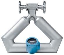
The mass flowmeter consists of three parts: a sensor, a transmitter, and a digital indicating accumulator. The sensor is made according to the Coriolis effect and consists of a sensor tube, an electromagnetic driver, and an electromagnetic detector. The electromagnetic driver causes the sensor to vibrate at its natural frequency, and the introduction of the flow causes the u-shaped sensor to be distorted by the Coriolis force and produce a phase difference between its left and right sides. According to the Coriolis effect, the phase The difference is proportional to the mass flow. The electromagnetic monitor converts the phase difference into a corresponding level signal and sends it to the transmitter, after filtering, integration, amplification and other power processing. It is converted into a 4-20mA analog signal proportional to the quality and a range of frequency signals.
The measurement principle of the mass flowmeter is based on Newton's second law of motion. F=ma type F-fluid force; m-measured medium mass; a-acceleration.
When the fluid passes through two parallel measuring tubes, an acceleration in the direction of the flow velocity and the corresponding Coriolis force are generated. This force causes the measuring tube to oscillate and distort. This distortion phenomenon is called Corio Profit phenomenon.
According to Newton's second law of motion, the amount of distortion of the measuring tube is directly proportional to the size of the mass flow through the measuring tube. When the fluid flows through the measuring tube, the fluid is subjected to the Coriolis force and the fluid in the measuring tube is subjected to the reaction of the Coriolis force to produce a phase difference between the inlet and the outlet. When the fluid is zero, the measuring tube oscillates at the natural frequency, the measuring tube is not distorted, and the phase difference between the fluid inlet and the outlet is zero. When the fluid flows through the measuring tube, the vibration of the tube at the inlet is decelerated, the vibration of the tube at the outlet is accelerated, and the phase difference between the inlet and the outlet occurs. The phase difference also increases as the mass flow increases. The phase difference can be measured by electromagnetic signal detectors mounted on inlet and outlet measuring tubes.
Second, the characteristics of mass flowmeter:
 No theoretical or artificial experience correction of the indication;
 The output signal is only proportional to the mass flow and is independent of the physical properties of the flow (such as temperature, pressure, viscosity, Reynolds number, etc.);
 Independent of environmental conditions (such as temperature, humidity, atmospheric pressure, etc.)
 It only needs to detect and process a signal (that is, the output signal of the instrument) to perform remote transmission and control.
You only need one variable to integrate time, so the total flow is simple and so on.
Third, the working environment
Working environment temperature limit is -37oC - 60oC